Nimbra 410 and 520 quickstart guide #
Overview #
This document is a quick start guide for Nimbra 410 and Nimbra 520
Intended Reader #
The guide is intended for service personnel performing hardware installation and maintenance, including initial software configuration.
Support and assistance #
If you have questions about how to use your equipment or software, and if you do not find the solution to your problem in this manual, please contact your local equipment and support supplier. For remaining questions, use https://netinsight.net/contact-us/
Conventions used in this manual #
To enhance the readability, the following font, syntax, and symbol conventions are used.
Information of specific importance #
ℹ Note: Details worth noting for proper function and enhanced utilization are seen within a frame like this.
Names of concepts and user interface details #
Terms and user interface names are in bold
Web navigation is logically separated by a pipe menu | page
Getting started #
Unpacking and Inspection #
Inspect the unit upon reception and notify the carrier and dealer if there is any damage. Save the packaging for future use or dispose of it properly.
Accessing the Web Interface #
The Nimbra appliance can be connected to your network using either DHCP (automatic) or static IP configuration.
ℹ Note: See The Specification for port names and details.
Option 1: DHCP #
- Connect the Nimbra appliance to your network using eno2, eno3, eno4, sfp1, or sfp2
- Prefer ports highlighted with a solid line (10 Gb/s or 25 Gb/s)
- Ports highlighted in a dashed line work too (2.5 Gb/s)
- Find the assigned IP address through your DHCP server
- Open a web browser and navigate to the assigned IP address


Option 2: Static IP #
- Connect your PC directly to the eno1 port using an Ethernet cable
- Configure your PC to use an IP in the 192.168.125.0/24 range
- Open a web browser and navigate to http://192.168.125.125


Initial Configuration #
Log in #
- Username:
admin - Password: Found on the chassis label
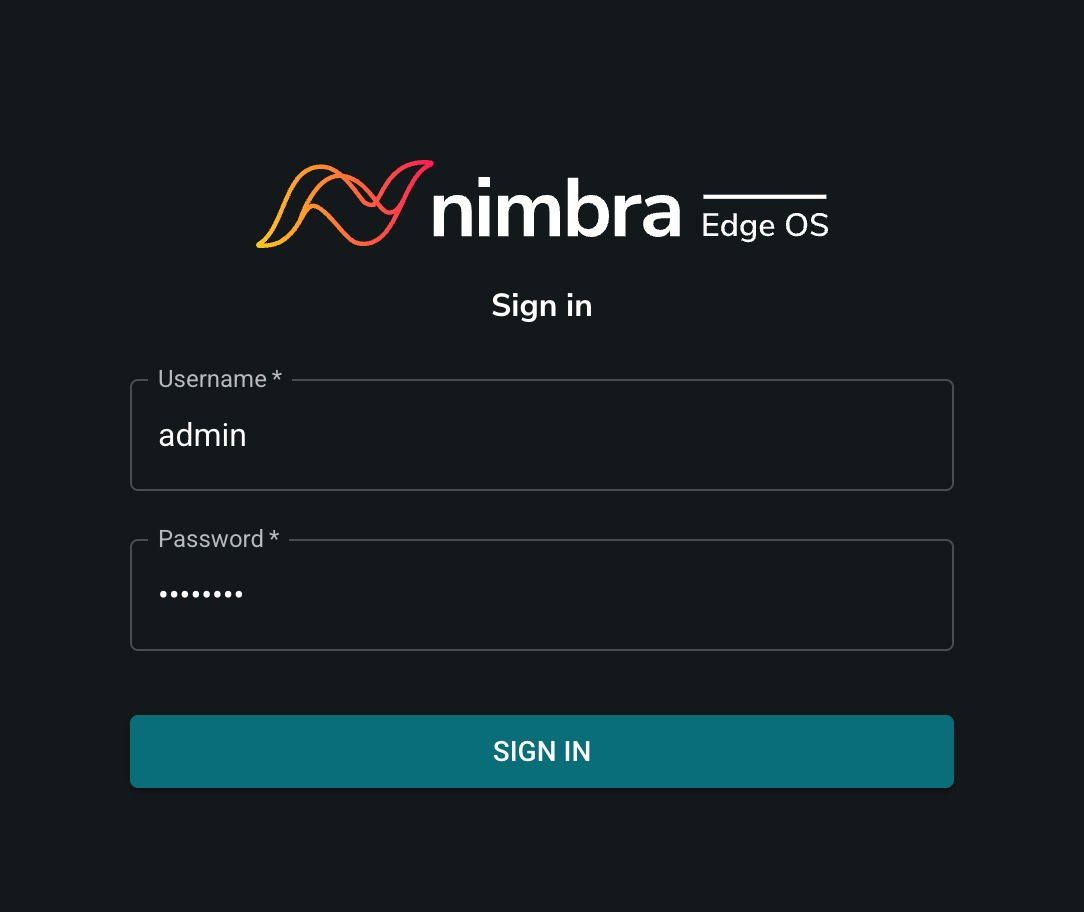
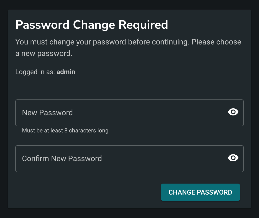
Change the default password #
Once logged in you will need to change the default password
Configure network (if needed) #
If your network requires specific settings beyond the default settings:
- Select Network | Interfaces in the left menu
- Configure your desired network settings
- Click Save changes
Connect to Nimbra Edge #
To connect your appliance to an existing Nimbra Edge installation:
You will need:
- URL to your Nimbra Edge installation
- Device name of your choosing
- Appliance secret
Steps:
- Select Edge in the left menu
- Enter your Nimbra Edge details
- Save the connection settings
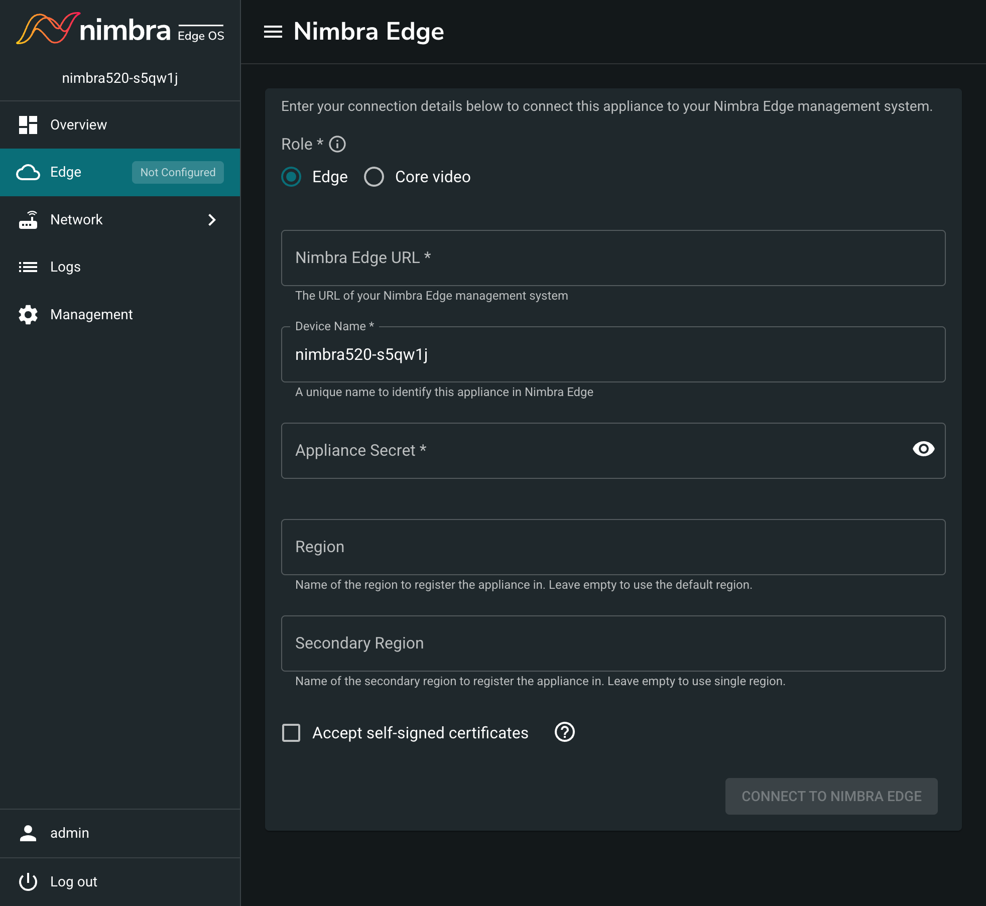
Your appliance should now appear in your Nimbra Edge cluster.
Factory Reset #
A factory reset restores the Nimbra appliance to its original factory defaults, erasing all configuration data and returning the system to its initial unconfigured state.
⚠️ Warning: Factory reset will erase all configuration data including network settings, passwords, and Edge Connect configuration. This action cannot be undone.
Using the Web Interface #
If you have access to the web interface:
- Log in to the web interface
- Select Management in the left menu
- Click the FACTORY RESET button
- Confirm the action when prompted
Using the Power Button #
To trigger a factory reset press the power button 5 times within 3 seconds.
Rack Installation #
Installation Requirements #
It is recommended that the Nimbra appliance be mounted in a 483 mm (19-inch) rack using a rack mounting kit. For other types of racks, please consult your local sales contact or Net Insight directly.
It is important that the chassis of the unit, the rack, and other external equipment are accurately grounded and have the same electrical potential.
Environmental Requirements #
| Requirement | Specification |
|---|---|
| Operating Temperature | 5 to 40°C (41 to 104°F) |
| Relative Humidity | 8 to 90% (non-condensing) |
| Location | Clean and dust-free location |
ℹ **Note: ** This product is for installation only in a Restricted Access Location (RAL). This restricted area should be a location for the equipment where access can only be gained by service personnel or users who are instructed about the restrictions and precautions that must be taken. Access to the restricted area shall only be possible using a special lock and key, or other means of security.
⚠️ Warning: Operation of this equipment in a residential environment could cause radio interference.
ℹ **Note: ** Leave approximately 760 mm (30 inches) of clearance in the back of the rack to allow for sufficient airflow and ease in servicing.
Mechanical Requirements #
| Dimension | Metric | Imperial |
|---|---|---|
| Height | 43 mm | 1.7 inches |
| Width | 437 mm | 17.2 inches |
| Depth | 455 mm | 17.9 inches |
| Rack mounting | 483 mm | 19 inch |
Rack Installation #
Preparing the Unit for Setup #
The box, in which your chassis was shipped, should include two sets of rail assemblies, two rail mounting brackets, and mounting screws. All are needed to install the system into the rack.
Rack Mounting Instructions #
Overview #
This section provides information on installing the chassis into a rack unit with the rails provided.
There are a variety of rack units on the market, which may mean the assembly procedure will differ slightly. You should also refer to the installation instructions that came with the rack unit you are using.
ℹ **Note: ** This rail will fit a rack between 660 mm (26 inches) and 838 mm (33 inches) deep
Rack Mounting Kit #
The chassis package includes two rack rail assemblies in the rack mounting kit. Each assembly consists of two sections: an inner fixed chassis rail that secures directly to the unit chassis and an outer fixed rack rail that secures directly to the rack itself.
Locking tabs #
Both chassis rails have a locking tab. The tabs lock the unit into place when installed and pushed fully into the rack. These tabs also lock the unit in place when fully extended from the rack. This prevents the server from completely coming out of the rack when you pull it out for servicing.

Reinstalling the inner rails #
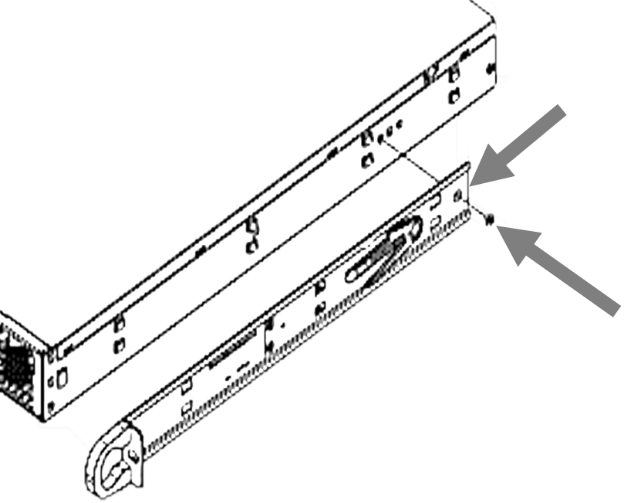
The inner rails are pre-attached to the chassis. If you need to remove them, reinstallation of the rails is simple and can be accomplished with a standard head screwdriver.
-
Place the inner rail on the side of the chassis, aligning the hooks of the chassis.
-
Slide the extension toward the front of the chassis.
-
Secure the chassis with one screw as illustrated.
-
Repeat steps 1-3 for the other inner rail.
⚠️ Warning: Do not pick up the unit by the front handles. They are designed to pull the system from a rack only.
Installing the outer rack rails to the rack #
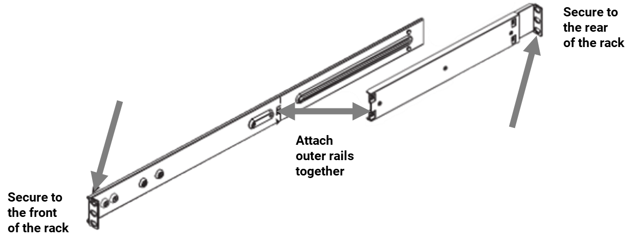
Outer rails attach to the server rack and hold the unit in place. The outer rails for the chassis extend between 660 mm (26 inches) and 838 mm (33 inches).
-
Attach the short bracket to the outside of the long bracket. Align the pins of the rail with the slides. The ends of each bracket must angle in the same direction.
-
Adjust both the short and long brackets to the proper distance so that the rail fits snugly into the rack.
-
Secure the long bracket to the front side of the outer rail with two M5 screws and the short bracket to the rear side of the outer rail with three M5 screws.
-
Repeat steps 1-3 for the remaining outer rail.
Installing the chassis into a rack #
-
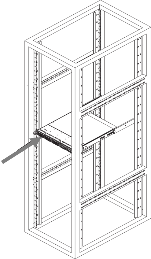
Confirm that the chassis includes the inner rails and rail extensions. Also, confirm that the outer rails are installed on the rack.
-
Align the chassis rails with the front of the rack rails.
-
Slide the chassis rails into the rack rails, keeping the pressure even on both sides (It may be necessary to depress the locking tabs when inserting). When the unit has been pushed completely into the rack, the locking tabs will “click” into the locked position.
-
Optionally, insert and tighten the thumbscrews holding the front of the server to the rack.
Installing the chassis into a mid-mount position (telco) rack #
-
Use the two L-shaped brackets (four total) to suspend the sides of the chassis within the rack.
-
Determine how far the chassis will extend out to the front of the rack. Larger chassis should be positioned to balance the weight between front and back. If a bezel is included on your unit, remove it.
-
Attach the two front brackets to each side of the chassis, then the two rear brackets positioned with just enough space to accommodate the width of the telco rack.
-
Finish by sliding the chassis into the rack and tightening the brackets to the rack.
Grounding #
A reliable ground must be maintained at all times. To ensure this, the rack itself should be grounded. Particular attention should be given to power supply connections other than the direct connections to the branch circuit (such as the use of power strips and so on).
Professional documents on grounding techniques include:
-
ANSI/TIA-942 – Telecommunications Infrastructure Standard for Data Centers
-
J-STD-607-A-2002 – Commercial Building Grounding (Earthing) and Bonding Requirements for Telecommunications
-
IEEE Std 1100™-2005 (IEEE Emerald Book) – IEEE Recommended Practice for Powering and Grounding Electronic Equipment
Specification #
Front Layout (All Models) #
On the front, there is one LED and one Power On/Off button.
Rear Layout #
Nimbra 410 #
All connections to the unit are made from the rear.
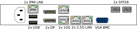
On Nimbra 410, the rear includes
- One Ethernet RJ-45, IPMI dedicated LAN
- Two USB ports
- Two display ports, DP
- Two Ethernet RJ-45 for 10 Gb/s LAN
- Two Ethernet RJ-45 for 2.5 Gb/s LAN
- Two SFP28 for 25 Gb/s LAN
- One VGA for Baseboard Management Controller, VGA BMC
- A LED indicating the status of the board.
Nimbra 520 #
All connections to the unit are made from the rear.
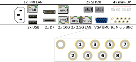
On Nimbra 520, the rear includes
- One Ethernet RJ-45, IPMI dedicated LAN
- Two USB ports
- Two DisplayPort, DP
- Two Ethernet RJ-45 for 10 Gb/s LAN
- Two Ethernet RJ-45 for 2.5 Gb/s LAN
- Two SFP28 for 25 Gb/s LAN
- One VGA for Baseboard Management Controller, VGA BMC
- Nine BNC ports (eight SDI/ASI and one sync port), Micro BNC
- Four Mini DisplayPort (non-functional) mini-DP
- A LED indicating the status of the board.
SDI Port Capabilities #
Most SDI connectors carry signals up to 3G-SDI (1080p). A subset of the SDI connectors are 12G-SDI capable and can additionally carry single-link 4K UHD (2160p). The 12G-SDI capable ports are:
| Model | 12G-SDI / 4K (2160p) capable ports | Remaining SDI ports |
|---|---|---|
| Nimbra 520 | SDI 1 and SDI 5 | up to 3G-SDI (1080p) |
| Nimbra 414 | SDI 1 | up to 3G-SDI (1080p) |
ℹ Note: In Nimbra Edge, 12G-SDI capable ports are marked with a 12G badge in the interface list and the interface selector, so you can identify them when creating an input or output.
Network Interfaces (All Models) #
Both Nimbra 410 and 520 have 7 network interfaces. Six interfaces (eno1-eno4 and sfp1-sfp2) are used by the application, while the last serves as an out-of-band management port (IPMI).
By default, eno1 has a static IP address only (no DHCP), while eno2-eno4 and sfp1-sfp2 support DHCP. IPMI also has a static IP address configured.
The default interface configurations are detailed in the table below.
| Interface | IP address | DHCP | Netmask | Capacity |
|---|---|---|---|---|
| eno1 | 192.168.125.125 | no | 255.255.255.0 | 2.5 Gb/s |
| eno2 | - | yes | - | 2.5 Gb/s |
| eno3 | - | yes | - | 10 Gb/s |
| eno4 | - | yes | - | 10 Gb/s |
| sfp1 | - | yes | - | 25 Gb/s |
| sfp2 | - | yes | - | 25 Gb/s |
| IPMI | 192.168.2.10 | no | 255.255.255.0 | 1 Gb/s |
IPMI (All Models) #
The IPMI interface is used for platform management. It is not to be used for media transport or application management.
If you need to log in to the IPMI interface, the user is ADMIN in capital letters
and the password is on the label on the chassis.
You will find this web page different from the application web pages, and that the
application itself is not reachable from the IPMI interface.
Button and Front LED (All Models) #
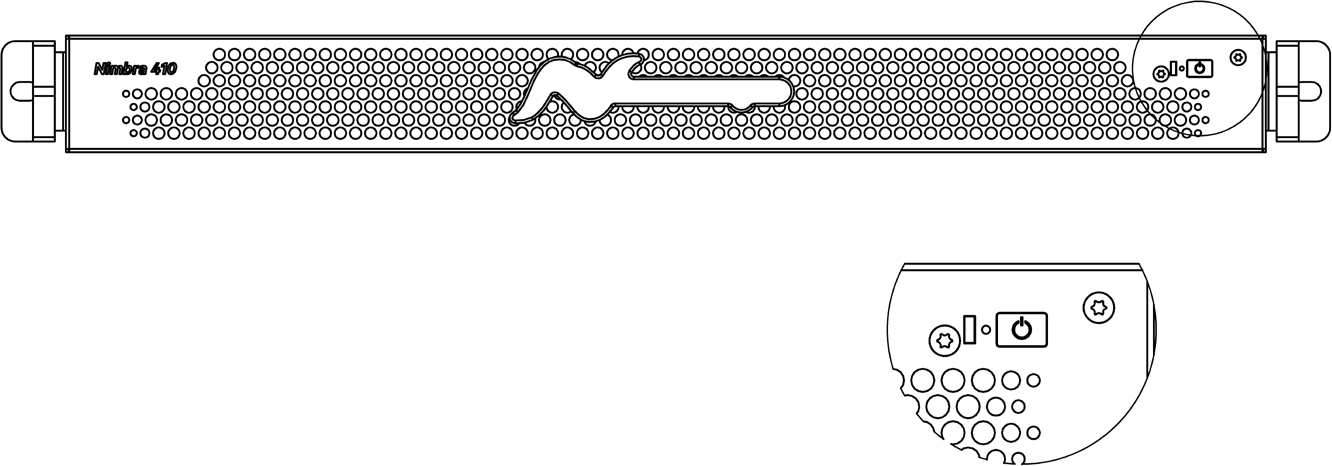
There is one LED on the control panel that provides system status and one Power On/Off button.
The main power switch is used to apply or remove power from the power supply to the unit.
ℹ **Note: ** Turning off system power with this button removes the main power but keeps standby power. Therefore, you must unplug the system before servicing to avoid damaging yourself and/or the equipment.
ℹ **Note: ** The button needs to be pressed for about 5 s before the unit is powered down. Hence, an accidental touch of the button is not enough to power down the unit.
The LED indicates the status of the system and should normally be illuminated when the system is operating.
Power (All Models) #
One 800 W high-efficiency power supply
| Specification | Value |
|---|---|
| AC Input | 100-240V / 10-5.5A / 50-60Hz |
The chassis is prepared for two power supplies. The power supplies are auto-switching capable. If the system includes a redundant power supply, it is hot-swappable and can be changed without powering down the system.
Environmental Requirements (All Models) #
| Requirement | Specification |
|---|---|
| Operating Temperature | 5 to 40°C (41 to 104°F) |
| Storage Temperature | -40 to 70°C (-40 to 158°F) |
| Relative Humidity | 8 to 90% (non-condensing) |
| Location | Clean and dust-free location |
Physical Dimensions (All Models) #
| Dimension | Metric | Imperial |
|---|---|---|
| Height | 43 mm | 1.7 inches |
| Width | 437 mm | 17.2 inches |
| Depth | 455 mm | 17.9 inches |
| Rack mounting | 483 mm | 19 inch |
| Weight | 8 kg | 18 lbs |
Safety #
There is a battery in the enclosure. For this battery, there are some necessary precautions.
⚠️ ATTENTION ! Il y a danger d’explosion s’il y a remplacement incorrect de la batterie.
Remplacer uniquement avec une batterie du même type ou d’un type équivalent recommandé par le constructeur.
Mettre au rebut les batteries usagées conformément aux instructions du fabricant
⚠️ ATTENTION ! To completely remove applied voltage to the device, the power cord must be unplugged. The mains plug serves as the disconnect device and shall remain readily operable.